
DIY Calibrator
Goal of this project is to build a circuit for generation of all necessary voltages, currents and resistances and signals needed to calibrate a 3478A multimeter. This means I have to generate a reference voltages of 300V, 30V, 3V, 300mV and 30mV, a constant current of 1A and 100mA, and resistance values of 30Mohm, 3Mohm, 300kOhm, 30kOhm, 3kOhm, 300Ohm, 30Ohm. My main design criteria was to try to only use older parts which I had already at home in my parts box. Mainly to save money, to use my stock, and also as a challenge to see what I can achieve with the items I have. This of course means that I will not get the best possible performance from the result, but I also think that the outcome will still be good enough for my hobbiest use.
300V
 One word of warning: Especially the 300V reference circuit and the high voltage present in combination with the output decoupling capacitor pose a deathly risk. Only build, handle and
use this kind of circuitry if you completely understand all the dangers involved, always follow all safety rules and best practice! Also be careful with the mains voltage present in the unit.
I will not take responsibility for anything that could happen!
Generating the 300V output reference voltage from the low supply voltage is the most complex task in this project. The circuit consists of a free-running oscillator which drives a selfwound ferrite-rod based transformer. The output of the transformer is rectified and then used to charge the output capacitor.
The basic idea behind this circuit is shown in the Linear Technology application note 118 "High Voltage, Low Noise, DC/DC Converters" from Jim Williams. The used topology is called resonant Royer converter. I modified the circuits shown in the application note in certain aspects: I disliked to use a feedback winding and therefore I used a different kind of oscillator circuit. The bipolar transistors were replaced by Mosfets, and the output voltage control is done by controlling the supply voltage to the oscillator with the help of a bipolar transistor in emitter-follower configuration. My implementation uses a oscillation frequency of around 30kHz. A first test of the circuit in the open-loop configuration (that means without the control loop in place) showed that the necessary high voltage can be generated.
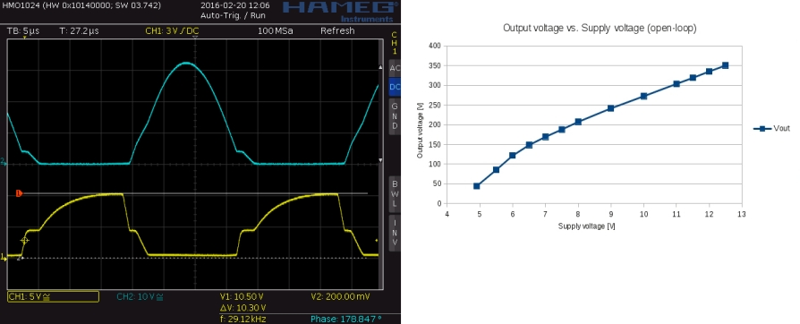 The oscilloscope picture on the left shows the MOSFET gate-source (yellow) and drain-source (blue) voltage waveforms during operation. Especially I wanted to make sure that
the gate-source voltages does not exceed the recommended maximum operating conditions. The relationship between measured output voltage and supply voltage is shown in the right plot.
The oscilloscope picture on the left shows the MOSFET gate-source (yellow) and drain-source (blue) voltage waveforms during operation. Especially I wanted to make sure that
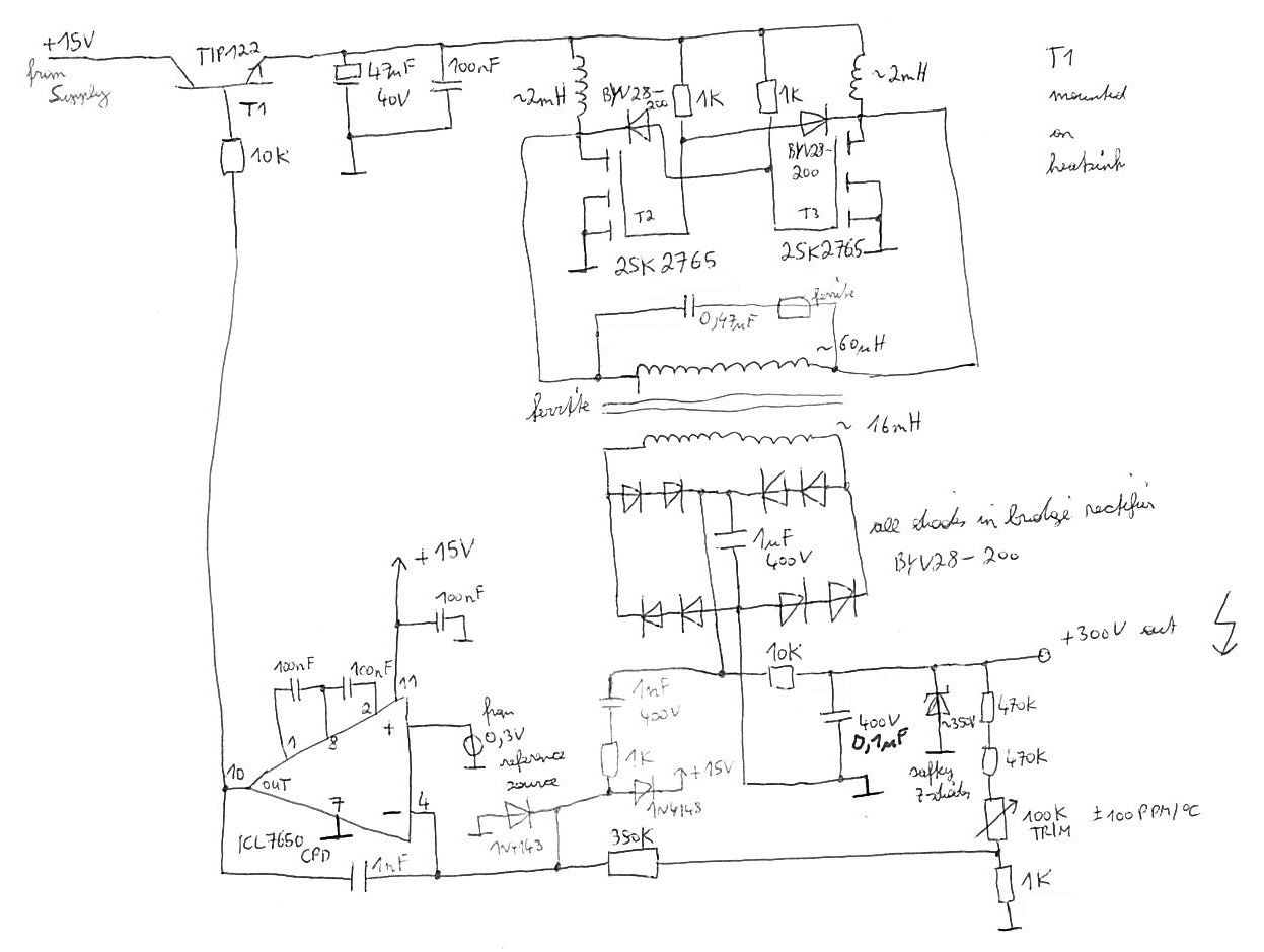
the gate-source voltages does not exceed the recommended maximum operating conditions. The relationship between measured output voltage and supply voltage is shown in the right plot.Next step was to add the control loop around the core circuit. A high ohmic resistive divider senses the current output voltage. The lower feedback voltage is then sourced into the error amplifier (Miller integrator), where the feedback signal is compared with the 300mV reference voltage signal on the positive input. My opamp of choice is an older now obsolete chopper-amplifier from Maxim Integrated Products with very low drift, and very low offset voltage. The output voltage of the error amplifier then controls the base voltage of the NPN power transistor, and with it the supply voltage for the core oscillator circuit. The series circuit consisting of the high voltage 1nF capacitor with a 1k series resistor which connects the negative input of the opamp with the bridge rectifier output is needed to stabilize the control loop. It is very important to also include the two 1N4148 opamp input-protection clamping diodes into this feedback path to prevent damage to the opamp. A ten-turn trimmer allows to precisely trim the output voltage, and a protection zener-diode at the high voltage output should protect the connected circuitry from overvoltage in case of a control loop error or overshoot. This safety zener-diode consists of a series connection of multiple lower voltage rated zener-diodes. The complete circuitry for 300V reference voltage generation is shown below.
30V
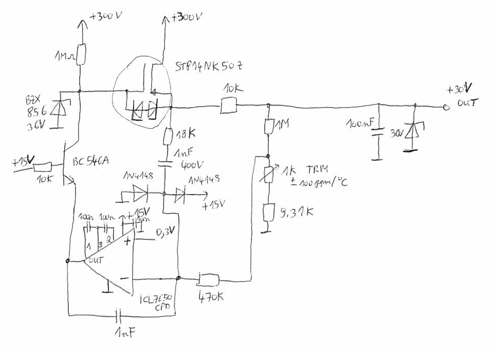
The 30V trimable output reference voltage is derived from the 300V reference output voltage by using a high voltage MOSFET pass device and a control loop. The output voltage is again sensed by a resistive divider, and a miller-integrator is used again as error-amplifier. A series connection of a feedback resistor and capacitor between the fast acting transistor output and the negative opamp input pin aids control loop stability again. Of course the two feedback clamping protection diodes are absolutely important again to protect the opamp from damaging spikes. A high-ohmic pullup resistor pulls the gate of the pass device higher and higher until the output voltage reaches the set target level, and then the opamp stabilizes and controls the gate voltage for constant +30V on the output.Care has to be taken how to connect the opamp output to the pass device. If the opamp output would be directly connected to the gate of the pass-device and the pull-up resistor it would be destroyed immediately, because it would not survive the high voltage levels present on the gate. The solution for this problem is to introduce another transistor in the common-base circuit configuration. This circuit makes sure that the highest voltage the opamp output can see is around 15V. Whatever current the opamp sinks at the emitter of the transistor also flows into the collector of the device. This current then controls the gate-voltage of the pass device, and with it the output voltage of the circuit. The 36V Z-diode at the gate makes sure that the gate-voltage is limited in case of a circuit malfunction or during startup, and this also makes sure that the allowed output voltage or the maximum rated Collector-Emitter voltage of the transistor at the gate is never exceeded. Another Z-Diode in parallel to the output is the last line of defense against overvoltage in case of a circuit malfunction.
I would recommend to use a pass device transistor with two protection z-diodes between the gate and the source. This makes sure that during startup or fast transitions the maximum allowed gate-source voltage is not exceeded. The first transistor I used had no protection diodes in place and after a fast output transition on the 30V output it was damaged and had to be replaced.
3V
A REF5030 voltage reference source from Texas Instruments is used to generate the 3V reference voltage. From this reference voltage all others output voltages and currents are derived. The REF5030 has not the highest possible initial accuracy, but it allows trimming, delivers the needed 3V, and is therefore perfect for my circuit. It can also sink and source a higher current, and therefore no additional buffer is needed for the 3V output. The REF5030 is suppplied by a linear 8V voltage regulator which helps to stabilize its supply voltage, and also should keep the disturbances on its supply line as low as possible.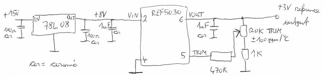
300mV
The 300mV source is pretty straightforward. A resistive divider on the 3V reference voltage is used to generate the needed 300mV voltage level. This voltage is then buffered by a simple unity gain buffer. This 300mV reference voltage also acts as the input reference voltage for the 30V and 300V reference circuit control loop.
30mV
The 30mV source is almost identical to the 300mV circuit. Only the resistive divider is modified to generate the needed lower reference voltage. And the power supply rail for the opamp is different. Only reason for this is that this circuit had to be moved to a second board, and on this board there is no +8V power supply rail present. Unfortunetly the +15V supply rail is more noisy than the +8V supply rail and therefore the noise on the 30mV output is worse than it could be.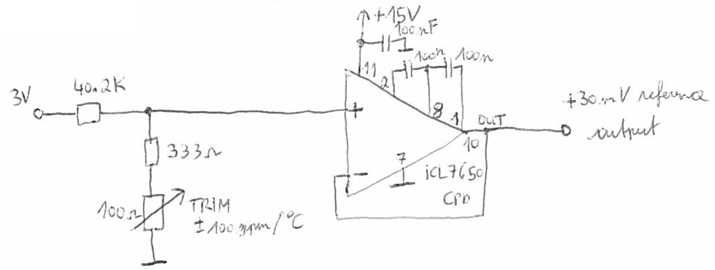
1A
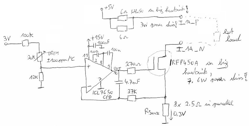
The generation of the 1A constant current is not a very complex task, but it generates almost all of the current consumption and power dissipation inside the calibrator. The first prototype derived the constant currents from the +15V supply rail, and the overall unit was using around 1.2A from this rail. Initially a 6 ohms series resistor was added to the 1A circuitry to approximately burn half of the necessary power dissipation inside the 1A current source to keep the transistor cooler. This resistor will also limit the current to save limits during a possible circuit malfunction, or during the initial inrush current when the load current output was open and is suddenly closed. Both the transistor and the series resistor had to dissipate around 7 Watts during operation at +15V.The first prototype was working and I was able to calibrate my first 3478A multimeter with it, but after one hour of continously operation of the unit its power supply overheated so much, that the bridge rectifier had to be replaced. After this event I decided that I have to bring down the power dissipation, and I decided to create the constant currents from a lower supply rail voltage. I also wanted to generate this new voltage with a step-down converter out from the +15V supply rail to decrease power draw from it. The final circuit only draws 0.5A from the +15V supply. Because the supply voltage for the constant current source was lowered also the series resistor was adjusted. The final circuit had much less power dissipation than the initial one.
To keep things cool the transistor and the series resistor are mounted on a bigger heatsink. The current flowing through the load is continously measured with a low-side current shunt resistor. Of course it is a good idea to keep the self heating of this resistor low for output current stability. Of course one could use a high performance resistor especially made for this purpose, but as I said before I wanted to use whatever I had. To reach the low resistance value I needed, to keep the self heating lower I decided to put more standard resistors in parallel. A parallel combination of 8 2.5 ohms resistors delivered me approximately the needed 0.3 ohms. While using a reference input voltage of 0.3V to the control loop this 0.3 ohms sense resistor will generate exactly the needed 1A constant current. The current flowing is again compared with an error amplifier consisting of an ICL7650CPD chopper amplifier. The opamp controls the gate voltage of the MOSFET transistor to achieve the set constant current level. The error amplifier is again implemented in the form of a miller-integrator. The current can be trimmed using a resistive divider on the control loop reference input. Without the 270 ohms resistor between the opamp output and the gate of the transistor the control loop was not stable and was oscillating. By adding this resistor the control loop was stabilized.
100mA
The 100mA constant current source is build exactly in the same way as the 1A current source, but here the power dissipation is not such an important topic anymore. By using a higher valued current sense resistor the set constant current is much lower.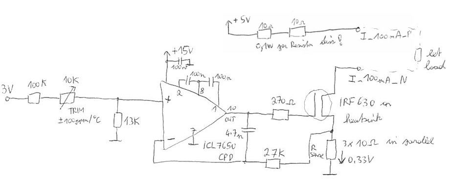
Resistance reference source
The 3478A can either be calibrated for 2wire or 4wire resistance measurement mode (not both at the same time). I will only use the normal 2wire mode, and therefore my calibrator only needs two terminals with the selectable reference resistance between them. Basically the whole circuitry does only consist of a rotary switch for range selection and a higher amount of different resistors to reach the needed nominal resistance values. A trimmer for each leg allows to trim the resistance to the final nominal value with good resolution. The whole stability and quality of this circuit will depend on the quality and performance of the used resistors. Because I did not want to spend money on special resistors and I am also ok with medium or poor performance for my hobbiest work I just took the best resistors I found in my parts supply box. If someone wants to reach better or good stability over time the whole construction style for the resistance reference circuit has to be made more professional.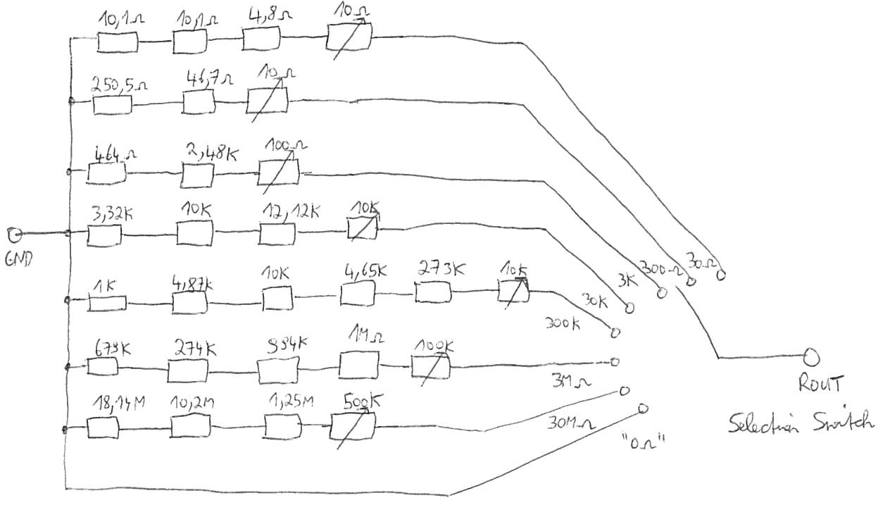
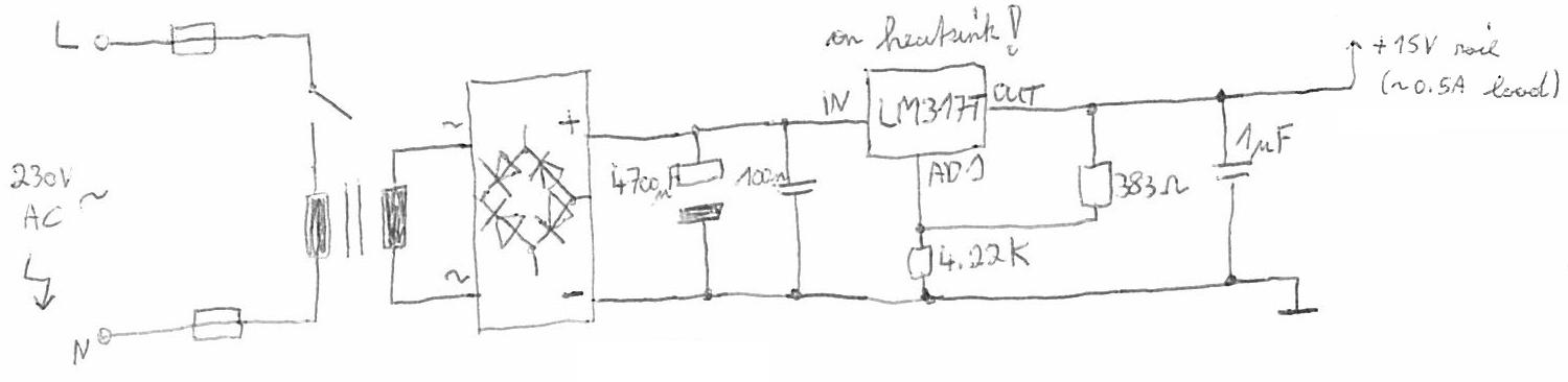
Power supply section
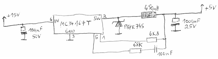
The overall calibrator needs around 0.5A at +15V. Because I had a transformer which does fit and also all the other necessary parts I went for a linear regulator solution based on the LM317T. To keep the linear regulator cool it was mounted on a heatsink. A heatsink is absolutely necessary at this load current levels. A full bridge rectifier and bigger smoothing capacitor are used to generate the input voltage to the linear regulator. Two feedback resistors for the LM317T set the output voltage to approximately +15V. The smaller capacitor very close to the input and output of the regulator keep everything stable. Last but not least a fuse on the primary side of the transformer keep everything safe in case of a problem, and a power switch allows to turn the unit on or off. After some time I decided that the +15V power supply still gets to warm for my liking, and this was when I decided to just add a small fan to the assembly to force cooling a little bit. Normally the last thing you want to add to precision circuitry is a fan and air flow, but I think in my case it will not really matter precision wise, and I prefer to run the components and the inside of the case cooler. The fan is a small 12V computer fan which is run by the +5V power supply to keep it very quiet and the air flow very low. It does the trick.The +5V power supply is based on a switching regulator I found in my parts bin. It is fixed internally to +5V output voltage which made it the perfect candidate. The +5V output rail is used to derive the 1A and 100mA constant current and to run the small fan for the main +15V power supply.
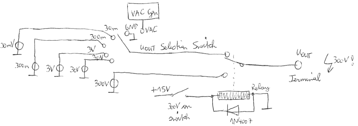
User interface
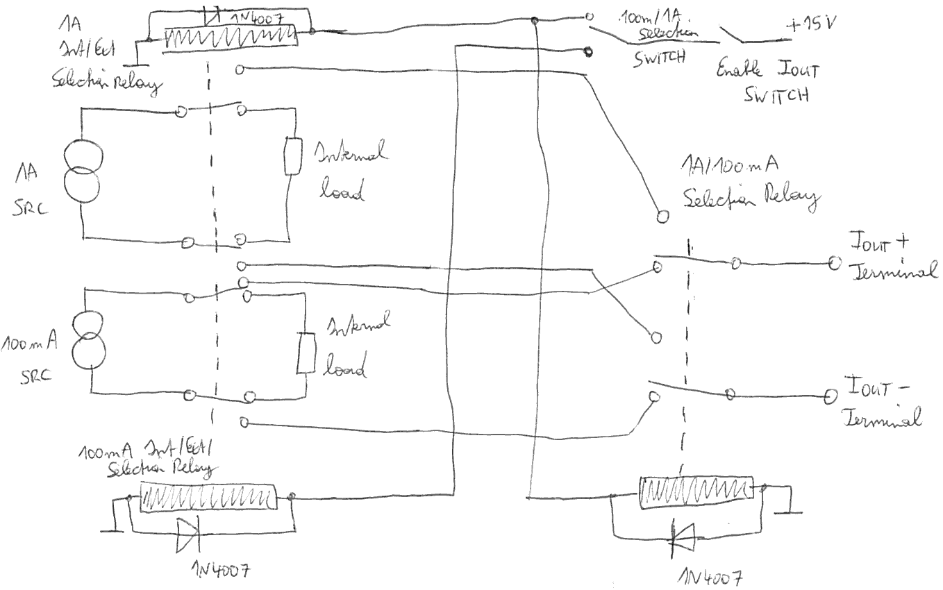
The user should be able to select the wanted output voltage, the wanted constant current and the output resistance with switches on the front of the chase. The output voltage is selected with a rotary switch. Because I did not want to use the front panel switch in combination with 300V I decided to add a relay which allows to output 300V if this option is selected, or whatever other safe and lower voltage is selected on the rotary switch by the user. This relay helps to isolate the user from the dangerous 300V source and will help to make the device a little bit more safer. Of course if an output voltage of 300V is selected the dangerous voltage is still present at the output terminal and the user has to be very careful to not touch anything! I used 24V relays which already switch reliable at the supply voltage of +15V. A freewheeling diode was added to every relay coil to make sure that no overvoltages are generated during switch off.The output voltage selection switch got an additional position which allows to short the positive output terminal with GND. The 3478A does not only need full scale range during calibration, but also needs a short on the input first to calibrate the offset. This additional switch position will help to make the calibration process more easy. The block called VACgen is the AC voltage calibration signal generator. If the switch is moved to this position then the AC calibration signal is connected to the positive voltage output terminal and the AC function of the multimeter can be calibrated.
For the constant current references I wanted to make sure that the references can still settle thermaly even when no multimeter or load is connected for calibration. That means I just have to switch the unit on and let it sit for some time, and because both current sources always are loaded the will settle to their final and stable opertion point. When an external multimeter or load is connected nothing changes for the operation point, and the current does not drift over time after finally connecting a load. To achieve this I added an internal load resistor for every constant current source, and a relay for every source selects if the output current is delivered to the internal load or should be connected to the output terminals. One additional relay at the output makes sure that under all possible circumstances both current sources stay always completely isolated from each other.
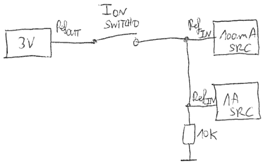
One switch allows to turn the current output off or on altogether. If this output is switched off then both current sources are loaded internally. One switch allows to select 100mA or 1A constant output current on the Iout+ and Iout- output terminals. To allow that the relays can be switched without current flowing and to prevent burning of the relay contacts over time I added an additional switch which allows to disable the constant current sources during the time the user want to make another selection. To switch off the constant currents the +300mV input reference voltage to the control loop of both sources is simply pulled down to GND. This then disables both output currents and the relays can safely be switched.
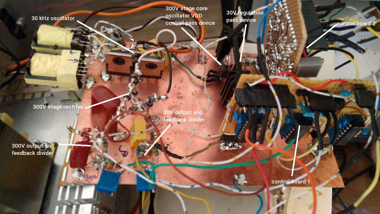
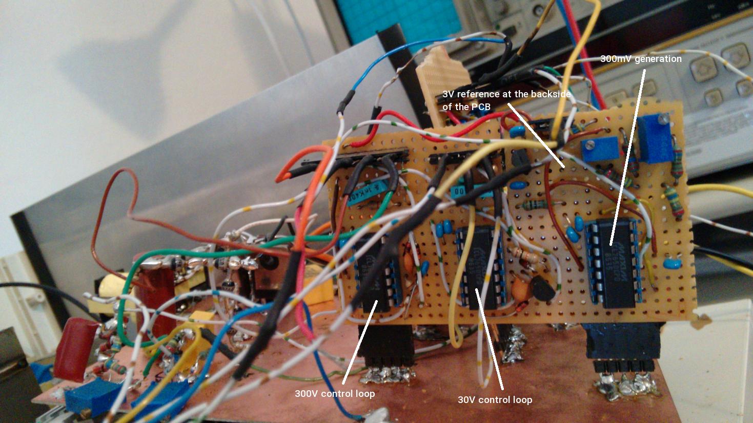
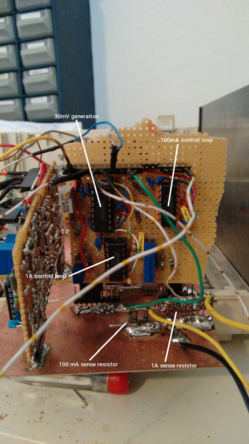
Construction
I did not want to invest the work and money to generate a layout for this project and to order a more professional PCB. I found a unused copper clad board and decided to mount and connect the bigger parts on it. It is a construction style I have not used before, but I think the result is not so bad. Of course if looks ugly, but at the end of the day what matters is a properly working unit. The copper clad surface forms the GND plane. The control circuitry was built on 2 smaller PCBs made out of veroboard. The two smaller boards are mounted on the main PCB with pin headers. This is not a very stable solution, but it allows remove the control boards for modifications.The main board and the two control PCBs generate all the reference voltage, and contain also the control loops for the two constant current sources. The remaining part of the two constant current sources is not shown on this pictures. The reference resistor section is located on a third PCB and will also be shown when finished. In a next step all of this boards will be mounted in a reused old housing with all the necessary selection switches and so on.
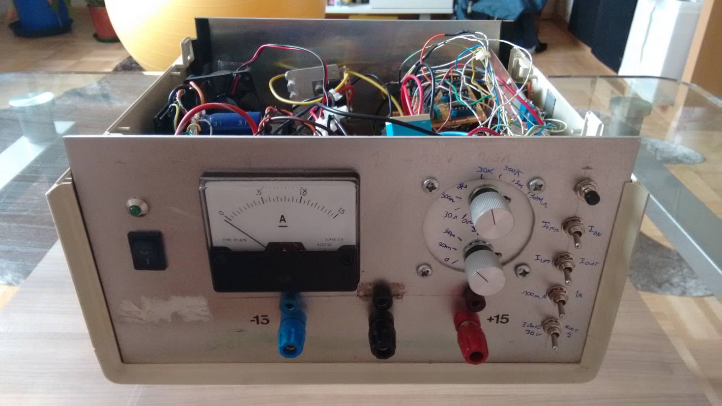
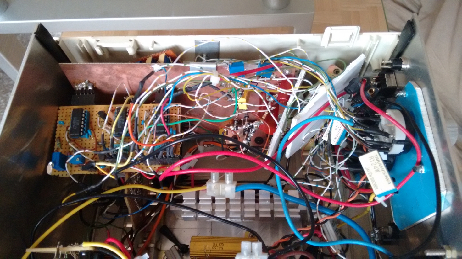
The final unit inside the reused old housing is shown below.

Measurements
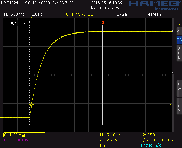
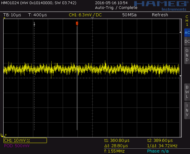
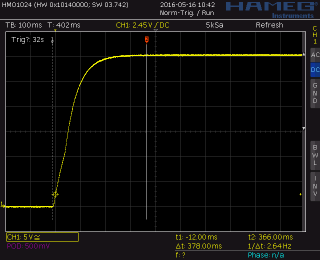
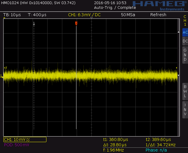
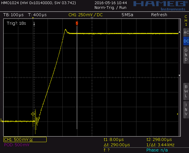
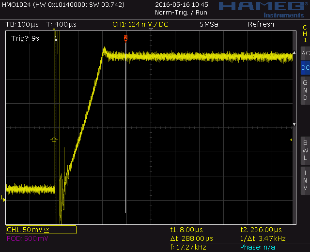
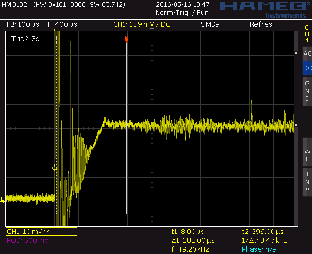
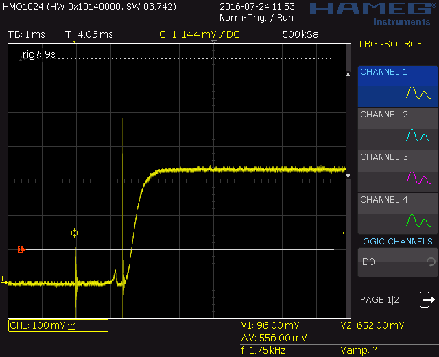
The following screenshoots from the scope show the behaviour of the circuits from above during startup and during static operation. It is not really the way how it should be done, but I made the startup measurements by simply connecting the power supply rail cable to the power supply output plug by hand. For the higher reference voltage this is not a problem, but especially for the 300mV and 30mV voltage reference one can see the spikes at the start of the rampup which are only generated by the contact "bouncing" during initial contact with the power supply output plug.But nevertheless one can see that all output voltages are stable, and that all the added control loops (300V, 30V) do not overshoot.
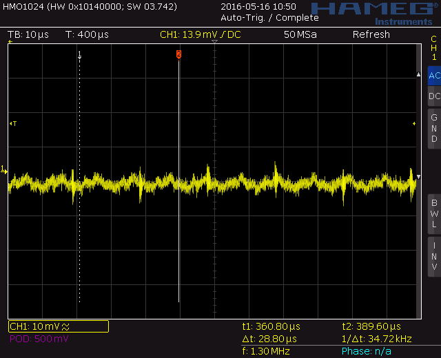
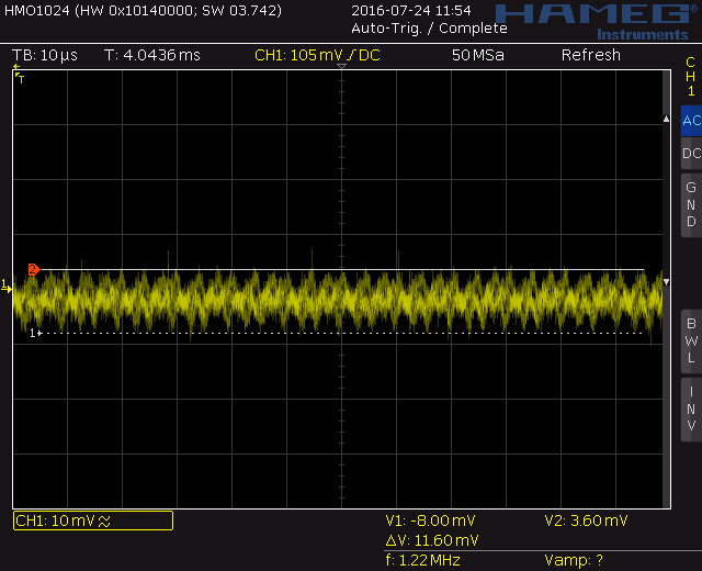
Also a word about the noise measurements on the right side. This graphs should be more considered as the worst case noise performance of the supplies, because to keep the measurements simple I used a passive probe with the original long GND clip cable. This means the GND connection was not optimized in any way, and into this bigger loop noise and disturbances are induced over the whole frequency range. Therefore in this measurements the true noise performance of the output voltages can not be seen, and it is most likely much better than shown here. But this measurements still prove that none of the output voltages are oscillating or are unstable.
300V:
30V:
3V:
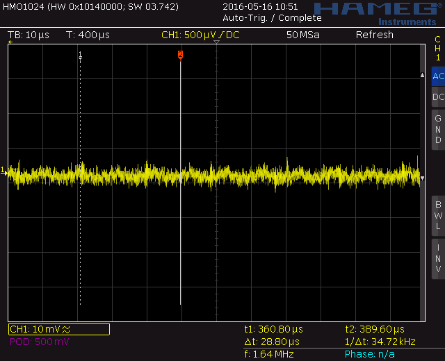
300mV:
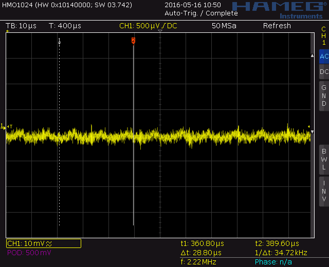
30mV:
The following two measurements for the constant current sources show the voltages on the low-side current sense resistors during startup and static operation.
100mA:
1A:


Result
Building all of this circuitry was far more work than I would have expected at the beginning, but this is something that is not unfamiliar. At the end I learned a lot during the process and I am really happy that I invested all of this effort. The most interesting finding during this work was that whatever part I needed I always found something useable in my parts box (except the switches and the 3V reference source). This is something I would never have expected.In the meantime I was able to use this unit to succesfully transfer the "calibration" of my Fluke 87 meter to my first repaired 3478A meter. Of course this is not a proper calibration in the professional sense (the Fluke 87 accuracy and resolution is far too worse to calibrate the 3478A properly) but it made my 3478A useful again for hobbiest usage. And this was the initial target.