Light control
I developed this circuit a long time ago in 2004 when we built a new carport. I was asked if I can built a circuit which takes care of controlling a light under the carport. The goal was a circuit which does the following:- A short push on a push button allows to switch on the light for a setable duration of time. After this time is over the light will turn off itself. If the light is already switched on a push on the pushbutton will simply restart the timing circuit.
- If the same push button is pressed for a certain longer time the circuit allows to switch on the light continuously. This operation mode is indicated by a LED, and the automatic switch off time function is disabled. The light will only turn off anymore when the pushbutton is again pressed for a longer time, which then stops this operation mode again, and after the setable duration of time has elapsed.
One last thing should be noted about this circuit: After some time I found one weakness of this shown implementation. When the circuit is powered up there is a small chance that the circuit starts in the "light continuously on" operation mode. This behaviour was mostly seen after thunderstorms triggered short power grid interruptions. Afterwards sometimes it was seen that the light is lit and it is not switched off anymore. I think it is very likely that this problem could be also solved by tweaking the reset timing component values, but because it was not a big deal for us I never bothered to solve this small bug.
Hardware

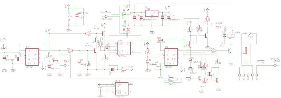
The schematic of the project is shown above. Because the control circuit needs much less power than the connected light I decided to go for two different fuses. The light is protected by a higher rated fuse, and the control circuit has a very weak fuse that makes sure that in case of a failure event the protection triggers immediately. The control circuit power supply section consists of a small transformer (mounted offboard), a simple bridge rectifier, and a 7805 linear voltage regulator. This generates the necessary +5V power supply rail.
The light is turned on using print relay K1, T6 and freewheeling diode D5. Timer IC3 takes care for switching the light off after the setable time duration. Potentiometer R12 allows to set the time duration. For a short push button activation transistor T3 takes care to discharge the timing capacitor C9 and to switch on the light. After C9 is recharge again IC3 will turn off the light again.
Positive edge-triggered D-flip flop IC2A stores the current state of the special "light continuously on" function. The D input pin is directly connected to FF output /Q. That means for every rising edge on the CLK input the output Q of the FF toggles. This means if we generate a pulse on the CLK input every time the push button is activated for a longer time period we can toggle the special function on and off with the push button. If the light is switched on continuously then output Q of IC2A is continuously high which then turns on transistor T5. This transistor makes sure that C9 can not be charged anymore and IC3 will turn on the light until IC2A is toggled and C9 is fully charged again. When this special mode is activated transistor T7 turns on an external LED in the push button housing to indicate this state.
The external push button is connected to terminals X1-1 and X1-2. Timer IC1 is used to debounce the push button and to make sure that IC2A can only be toggled once per activation event. Without this debouncing circuit it could happen that IC2A toggling does not work as expected. Timer IC1 also makes sure that we get a minimum length activation pulse for transistor T3 which is long enough to fully discharge capacitor C9. This makes sure that the light turn on time period is well controlled, and also that this turn on event works reliable. The RC combination R4 & C4 is used to detect and to set the time internal needed for the pushbutton activation to toggle IC2A and to switch the special function "light continuously on" on/off. If the pushbutton is pressed long enough the base voltage on transistor T1 gets high enough to turn this transitor on. This then generates the needed "toggle" pulse via T2 on FF IC2A CLK input.
Last but not least RC combination R9 & C5 should make sure that flip flop IC2A is disabled and has a defined state during statup of the circuitry. This is also the place where in my oppinion the last small bug which is described above could most likely be solved by modification of the time constant. But as I said I never actually tried solving this imperfection because for us it is a non-issue.
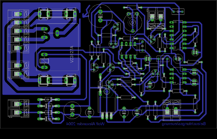
PCB design was again done in Eagle. The outcome was again etched, all the holes were drilled, and the circuit was built again by using through-hole components. The actual layout is shown below.

