DCC Accessory Decoder
Function
DCC (digital command control) is a digital communication standard used on model railroads which allows to transmit messages to a digital decoder inside the locomotive. This allows to control more locomotives on the same track because each locomotive only receives commands which fit their own DCC adress. Other than that DCC is also often used to control turnout decoders or to switch lights on and off an a model railroad layout. Therefore a very versatile standard. The DCC signal is generated by the control station, amplified by the boosters and then feed directly into the rails.The purpose of this module is to receive DCC messages for turnouts/lights from the track and use the information to control all the lights on the model railroad layout. Beside DCC I also added a second simple bus interface ("lightbus") to the module which allows the main computer to also control the lights via a serial interface. This was necessary because my own light control application will not have direct access to the DCC control station which is already connected to the railroad layout train control software.
Decoding DCC
The DCC protocol was defined by the Digital Command Control Working group of the National Model Railroad Association (NMRA). The standard and additional information can of course be found online. The digital signal on the track must firstly provide the necessary power to the engine and the DCC decoder inside the locomotive to be able to run them, and secondly the necessary digital control information which is then received to trigger the control events. Electrically speaking the signal on the track is a rectangular signal which changes between two voltages with opposite polarity. The average value of this signal is approx. 0V, and the positive and negative amplitude of the signal is of equal size. Depending on the mechanical scale of the railroad layout different amplitude levels are common, for example for H0 a voltage of +/- 16V seems to be common.The locomotive is using a bridge rectifier to generate a constant supply voltage from this DCC signal for running the decoder and the engine.
 The digital control information which is then received by the Accessory-Decoder (or locomotive decoder) are coded in the length of the rectangular pulses (that means how long the current signal polarity is maintained before the polarity changes again). Because of this kind of modulation it does also not matter in which direction a locomotive is put onto the tracks, the received information is the same.
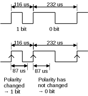
According to the DCC standard a high bit (1) equals a rectangular pulse with the duration of 58µs (period length 116µs). A low bit (0) has a minimum duration of at least twice the length of a high bit (therefore 232µs). A example signal is shown below.
The digital control information which is then received by the Accessory-Decoder (or locomotive decoder) are coded in the length of the rectangular pulses (that means how long the current signal polarity is maintained before the polarity changes again). Because of this kind of modulation it does also not matter in which direction a locomotive is put onto the tracks, the received information is the same.
According to the DCC standard a high bit (1) equals a rectangular pulse with the duration of 58µs (period length 116µs). A low bit (0) has a minimum duration of at least twice the length of a high bit (therefore 232µs). A example signal is shown below.To be able to decode a random sequence of bits an external interrupt of the AT89S52 is used in combination with a internal timer unit. Every rising edge of the DCC signal starts the internal timer. The timer fires again after 87us and requests an interrupt. Inside this interrupt routine the input level of the DCC signal is double checked again. If the signal polarity has changed already we have read a high (1) bit. If we still see the same polarity then a low (0) bit is received.
The firmware stores this received information in a buffer until a complete DCC frame/message was received. Afterwards this message is either rejected if we are not interested in it, or the necessary action is triggered.
It needs to be noted that an accessory decoder (which switches turnouts or lights, what I built) and a locomotive decoder listens to different frames/messages. A locomotive decoder needs to be able to receive far more different and more complex DCC messages (+Broadcast messages, for example emergency stop). The accessory decoder I implemented is only able to receive the absolute minimum amount of necessary message to work properly.
The format of the DCC message we need to be able to properly receive as an accessory decoder is shown below.

The firmware is receiving bit after bit and is waiting for a Start of frame (preamble) to happen. The firmware is doing this by counting the amount of sequentially received 1-Bits until the first 0-Bit is received. If before this first 0 bit at least 10 high bits were counted a new messages does start. If the amount of counted high bits is less than 10, or we received more than 14 high Bits then the firmware resets the counter and start counting again.
After a valid start of frame (preamble) was found the firmware continues to collect all received bits in a buffer until we have collected the full 3 bytes of information. After the last high Bit of the message the data processing is started. First the firmware checks if the checksum of the received message is correct. The checksum is calculated from the lower part of the adress (first byte), and from the second byte (command, higher part of adress). It should be noted that the high adress information in the second byte is transmitted inverted. The checksum itself is calculated using a XOR operation between this two parts. If the calculated checksum fits the received one in the message then the firmware continues with the processing, otherwise the message is rejected and ignored.
The next step is to combine the two parts of the adress information (high & low) and compare it with the accessory decoders own adress. If the received adress does not match the decoders own adress the message is not for us and is ignored. If we find a match than the message is further decoded and the necessary action is triggerd by switching the appropiate output driver. Which output should be switched to which new state is contained in the command section (CCCC) of the second byte(see below).
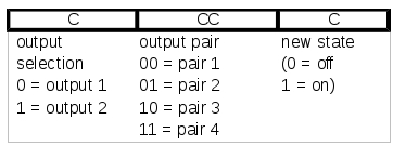
The information shown here was derived using the Lenz LZV100 command station and is most likely only valid for this digital system. For example while using Lenz the first bit of the CCCC information turned out to be not useful because it always contained exactly the same information (independent of the switch event). Therefore for Lenz the two middle bits select the signal (output pair) which should be switched to the new state, and the last bit contains the new state. For a signal a low bit (0) means for example red (stop) and a high bit (1) green (go). Depending on the used digital system (manufacturer) the meaning of this bits can be different. After all of this information is decoded the DCC decoder switches the correct output driver to the new received state.
Lightbus
The "Lightbus" allows me to control the lights also from my own PC application. The application will simulate the time of day and will turn on the lights in the houses accordingly. Goal is that the light behaviour looks as realistic as possible, that means that the lights in the houses or the streetlights will be switched on when it gets dark, and will be switched off at the morning.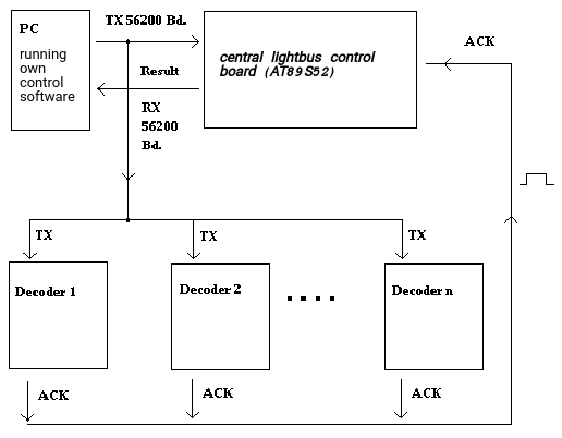 The lightbus itself is based on two optocoupled current interfaces (one for TX, one for acknowledge). The TX path is furthermore based on using a serial UART interface. The light switch commands are transmitted from the UART of the PC and then directly received by all of the DCC decoder boards. If the target adress fits
with the adress of the board the switch command is executed, otherwise the command is ignored. When the switch command message was properly received and executed by one of the DCC decoder boards this board then generates an acknoledge pulse on the second current interface.
The lightbus central board microcontroller senses this acknowledge pulse and then informs the PC about proper reception of the command. If the target adress was invalid or the message checksum was not correct no acknowledge pulse
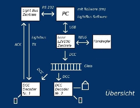
is generated by any DCC decoder board, and after a certain timeout time the lightbus central board microcontroller will inform the PC about the unsucessfull command transmission. Now the PC can retransmit the message if necessary. The lightbus architecture is shown in the picture on the left.
The lightbus itself is based on two optocoupled current interfaces (one for TX, one for acknowledge). The TX path is furthermore based on using a serial UART interface. The light switch commands are transmitted from the UART of the PC and then directly received by all of the DCC decoder boards. If the target adress fits
with the adress of the board the switch command is executed, otherwise the command is ignored. When the switch command message was properly received and executed by one of the DCC decoder boards this board then generates an acknoledge pulse on the second current interface.
The lightbus central board microcontroller senses this acknowledge pulse and then informs the PC about proper reception of the command. If the target adress was invalid or the message checksum was not correct no acknowledge pulse
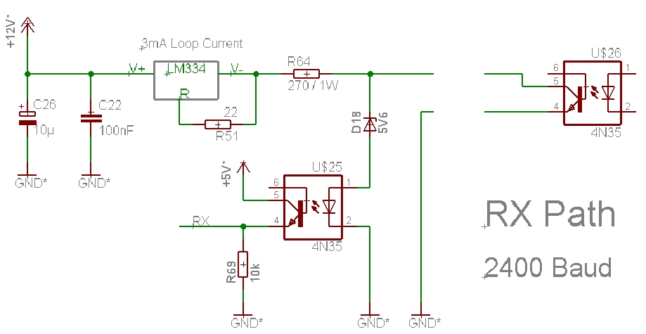
is generated by any DCC decoder board, and after a certain timeout time the lightbus central board microcontroller will inform the PC about the unsucessfull command transmission. Now the PC can retransmit the message if necessary. The lightbus architecture is shown in the picture on the left.The following pictures show the TX & RX circuitry of the lightbus on the lightbus central control board. The lightbus central control board itself is also shown on a picture further down on this page. The lightbus TX inputs of multiple DCC decoders are connected in series configuration. It has to be noted that the maximum number of inputs in series is limited by the available TX output voltage headroom. Because the amount of allowed inputs in series would not be enough for the whole railroad model train setup another PCB was designed which will later be used as a lightbus "repeater board". It receives the data and then splits it to additional current loops which then each can consist of additional inputs again. In this way the switch commands will reach every DCC decoder board in the setup. The RX (acknowledge) outputs of all DCC decoders are simply connected in parallel and are then connected back to the lightbus central control board. Here no limit has to be taken into account.

Hardware
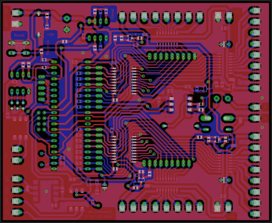
My hardware is again based on the AT89S52 microcontroller from Atmel. Attached is again an external I2C EEPROM to store the necessary adress and configuration information. A TL7705 supply supervisor takes care of the reset generation. All interfaces are optocoupled to make sure that I do not run into ground loop problems. Four 74LS373 latches are used as a port expansion and allow also to PWM modulate all LEDs independently in software to control their brightness. The lights itself are driven by four ULN2003 darlington transistor arrays. It should be noted that the output current capability of this driver is rather limited, and that I will only use it to drive LEDs. Because each ULN2003 driver only consists of 7 channels the missing last channel for a 8-bit port was added with discrete circuitry.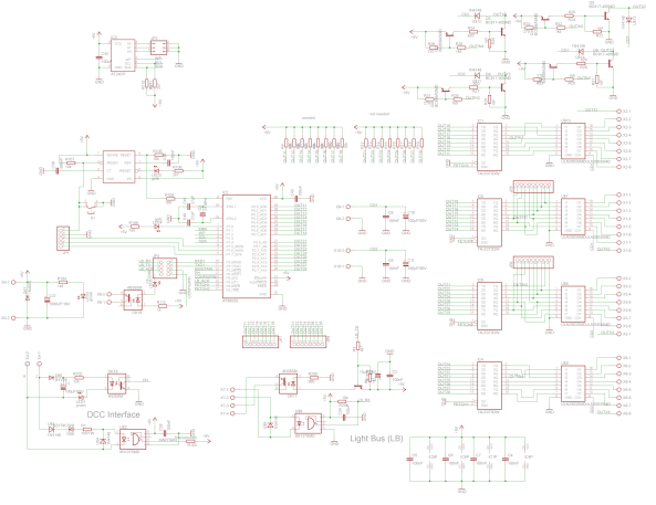
My own added serial interface is based on two current loops. One loop is for receiving data from the control PC with 57600 baud. The reception of messages is acknoledged via a return current loop which is rather slow in comparison. This allows the central computer to find out if a message for a certain light was received or not.
Firmware
The firmware was again developed in C. It decodes and handles DCC messages, and at the same time handles also control over my own serial bus system. Inbetween handling receive interrupts the microcontroller is busy with PWM modulation of all connected light outputs. Finally the firmware has a configuration mode again where the necessary configuration via RS232 can be done.Prototype PCB
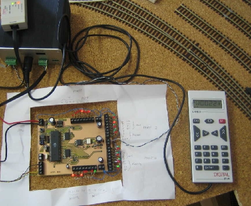
Initially a prototype PCB was built and the whole system was tested for proper functionallity. At this point in time I developed a Win32 console application which allowed to control the lights already via the PC automatically. The board was also decoding DCC messages from the digital system via the track and switching the signals accordingly. The whole first test setup is shown in the picture below containing the Lenz LZV100 command station, a Lenz LH100 throttle, the Lenz USB Interface connected to the PC, the Lightbus central control board connected to the PC via RS232 interface and last but not least the prototype DCC decoder board.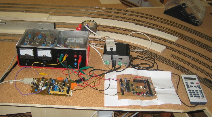
Final PCB
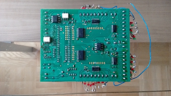
The prototype circuitry was improved by adding two additional buffers for two of the I/O ports which now allowed software PWM modulation of all the outputs independently. A new PCB layout was done knowing that this time the boards will be manufactured by a PCB manufacturing company. At the same time I developed a first Win32 GUI Application using the free LCC-WIN32 compiler doing the same as the initial Win32 console application, but in a much more user friendly way. The next two pictures show a finished PCB used for testing with a LED installed for each output channel. It should be noted that the PCB on this picture still needs to be cleaned from all the flux residue. Populating all parts by hand for 20 boards at home took quite some time and was a painstaking process.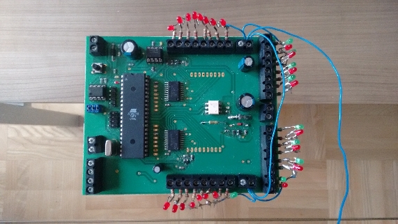
Win32 Application
Right now the lights on the model railroad layout are automatically controlled by a Win32 Application I programmed a long time ago. The application is not very good looking but it does the job as expected. It was compiled using the LCC-Win32 compiler.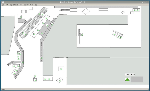
In Operation
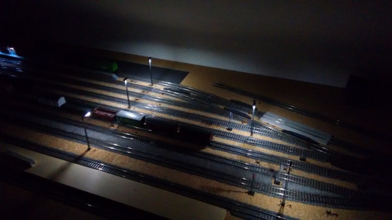
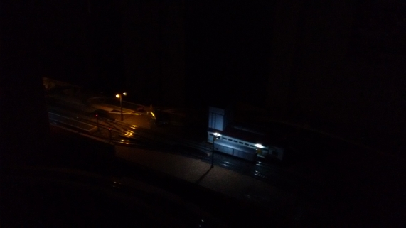
Light up buildings or the landscape makes a lot of fun. Two examples are shown below from our work in progress. Even though the landscape is not really started yet the light sources add a lot of atmosphere.