DCC (Lenz) loco decoder hints
Reason
This page summarizes some knowledge I gained about programming and using DCC locomotive decoders over the past years. Maybe this information will help somebody else to speed up the learning process. I made the mistake to not read the decoder manual in detail when I started to use them, and only quite some time later I figured out how much configuration there is in the decoder, and how much it will affect the behavior of the locomotive and how well it can be controlled via the computer.It is important to mention that I only have experience with the DCC decoders from the company Lenz, and that depending which decoder you use this information could be wrong for your case. But because I show only rather basic settings here (basic CV registers) which every DCC compatible decoder should be compatible with even then this page could be useful for you.
DCC decoder setup
Every DCC decoder contains non-volatile configuration registers/variables called CV registers which allow to change the behavior of the locomotive: for example what is the maximum speed, how fast does it accelerate or brake and so on. The most basic CV register is the decoder adress under which the locomotive will be adressed later. When a new decoder is installed it makes sense to tune the decoder behavior accordingly. This allows to get comparable behavior of locomotives if wanted, even though the have different behavior depending on its engine performance, different gear ratios and so on in the first place.CV1: (primary/short) locomotive adress
This CV contains the (primary/short) adress under which the locomotive decoder should receive commands. DCC defines two kinds of adressing possibility: A primary adressing scheme which allows to select locomotives with adress 1 up to 127, and an extened adressing scheme which allows over thousand locomotive adresses. Lenz decided to limit the short adress range from 1 to 99. If a locomotive in this range is adressed then the command station will control this locomotive by transmitting frames using the primary adress. If a locomotive decoder is configured to work within the short/primary adress range then it will compare the received adress with the value in CV1. If this data matches then the decoder will execute the received command.Because CV1 does not contain enough bits to store the extended adress two additional CV registers are used within the decoder to store its extendend locomotive decoder adress. Another CV register bit inside the decoder controls if the primary or extended decoder adress should be selected. In case the extended adress is selected CV1 has no function anymore.
CV2: Start voltage for engine
There are a lot of different engines types which will start to spin at different supply voltages. This CV controls the voltage which is applied to the engine for the first speed step. This value should be adjusted until the locomotive is moving with the desired minimum speed for the first speed step. If the value is to low the locomotive will not move at all or to slow. I have not actually seen this happening myself, but I also read somewhere that if this CV is too high it could happen that the locomotive is actual moving even if it is stopped.It is recommended that CV2 is configured right at the start, because it will have an effect on the maximum speed setting of the locomotive as well.
CV5: Maximum speed setting
Also the maximum speed that a locomotive can reach with the highest selected speed step will depent on its gear box ratio and the used engine. It could be that a locomotive is moving way too fast or too slow using the highest speed step that it looks unrealistic. The ideal case is that the highest speed setting selects a maximum physical moving speed which looks realistic for this model. This is also benefical because the range between the maximum and minimum speed is divided by the decoder into the selected amout of speed steps. For example using 28 speed step mode this range is divided into 28 selectable speeds. If for example the maximum realistic looking speed is already reached at half the speed steps, that means the locomotive is configured to be way too fast, then the upper half of the speed steps are not used anymore, with the side effect that the resolution in which the speed can be changed is twice as large for the lower usable portion as it must be.If CV5 is setup properly for the maximum speed that should be used and is realistic than the resolution of the speed selection is optimized. I would tune CV5 right after a proper value for CV2 was set (minimum speed for speed step 1). Please also note that a changed setting for CV5 will influence the minimum speed again slightly.
CV6: Mid speed setting
As already noted the range between the maximum and minimum speed is divided by the amount of selected speed steps. How this is done can be influenced with this CV6 setting. If CV5 is set lower then more speed steps are located in the lower half of the speed range. This also means that the resolution for higher speeds is decreased. If CV6 is set higher then the opposite effect will be achieved. And if CV6 is set to the mid value between the maximum and minimum speed value then a linear curve is set between the minimum and maximum speed. That means that every speed step increase increases the phyical moving speed by the same amount. As far as I know most computer software packages that control model railroads call for a linear speed curve as it allows better and more precise control of the locomotives.Note for Lenz: At least Lenz seems to specify CV6 relative to the value in CV5 (maximum speed). That means if CV6 should be set to mid value between the maximum and minimum speed to force a linear speed profile, its value have to be set to 50% of CV6. Because 100% for CV6 relates to a CV value of 255, the proper CV5 setting for this case is 128. Because I always want to force the linear speed profile I simply write 128 into the CV6 register.
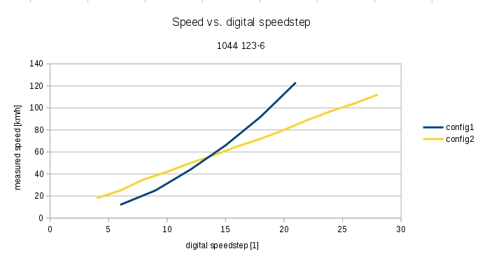
To better explain what CV6 does see also the following picture:

config1: CV2 = 01 (MIN), CV6 < 128 (MID), CV5 = 254 (MAX)
config2: CV2 = 06 (MIN), CV6 = 128 (MID), CV5 = 130 (MAX)
During configuration "config1" of the loco decoder the mid speed setting (CV6) was lower than 128. This has the effect that the loco speed profile is not linear anymore, and the lower speed settings deliver smaller increments in speed while the higher settings have bigger increments between adjacent speed steps. Please also note that the maximum speed for "config1" would have been much higher than for "config2" because the max speed setting was much higher here. But because "config1" was not measured up to the maximum speed step the maximum speed can not be seen here.
For "config2" the loco decoder mid speed setting (CV6) was exactly 128. So we expect a linear speed profile which was verified by a speed profile measurement. This means between all adjacent speedsteps we get the same increment in speed. Also the maximum speed setting CV5 is now at its sweet spot, because we reach our target for the maximum speed exactly at the maximum digital speed step. This means the resolution of the speed is as good as it gets.
The case where CV6 > 128 is not shown here, but it would create exactly the opposite effect of "config1".
Weird speedprofiles are possible
If your locomotive shows unexpected behaviour in the speedprofile then often a bad (unlucky) setting of the Mid speed (CV6) could be the culprint. I for example had one case where an increase in the current speedstep setting at lower speeds actually decreased the locomotive speed further. Only for higher speed settings the speed of the locomotive increased again. In this case a different setting for CV6 solved the problem completely and the speed increased over all speed settings as expected.During operation
Shunting speed (often F3 on Lenz decoders)
If your locomotive unexpectedly drives slower or the speedprofile is much lower than normal it could be that you accidently engaged the "shunting speed" function of your Lenz decoder. If this function (which in most cases is F3) is enabled then the locomotive only drives half of the otherwise expected speed. This allows to even reach lower speeds with your locomotive during shunting.Negative effect could be that a software which uses the premeasured speedprofile of the locomotive to control it and brake it automatically is not able to function properly anymore as the speedprofile is now completely different. This is why I want to mention this function here as I was not aware of it from the beginning. By switching F3 off again the locomotive drives the usual higher speed again.
If the light misbehaves
If your locomotive front and rear facing lights randomly switch on/off when you change the current speed or can not be switched on/off at all a likely reason is that the locomotive decoder is configured to use a different maximum number of speedstep setting as the digital station is currently configured to for this specific decoder adress. This means the digital station transmits the speed and light information in the wrong format for the decoder and this is why often the light starts to act up as a first indication.If this is the case check if the locomotive decoder setting fits with the current digital command station setting for this locomotive.
Example speedprofiles
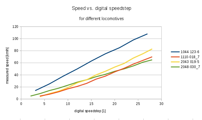
The following graph compares some of your locomotives speedprofiles after the decoder was finally setup. This should be an example how initially different behaving locomotives can be tuned accordingly to reach a target behavior. The maximum speed of the 1044 was set higher on purpose. The other locomotives will only be moved more slowly over the model railroad setup.
1044 123-6: CV2 = 06 (MIN), CV6 = 128 (MID), CV5 = 130 (MAX)
1110-018_7: CV2 = 10 (MIN), CV6 = 128 (MID), CV5 = 04 (MAX)
2043 019-5: CV2 = 06 (MIN), CV6 = 128 (MID), CV5 = 05 (MAX)
2048-030_7: CV2 = 04 (MIN), CV6 = 128 (MID), CV5 = 120 (MAX)
How is this speed defined?
The speed in [km/h] on the y-axis would be the speed a real locomotive drives in the real world if it drives the same speed as the scaled down locomotive on the scale down model railroad layout [often refered to in cm/s]. Of course both figures are linked to each other and can be calculated from each other. The scaling factor (for us H0, 1:87) will also be part of the equation for conversion. Most model railroad layout control software I know takes speed in term of "real world" locomotive driving speed in [km/h]. From this the software is able to calculate the necessary speed in [cm/s] for your scaling factor.For example to calculate the speed in [cm/s] on the model railroad layout in H0 (1:87) from the "reallife" speed in [km/h] the following equation can be used:
speed_in_cm_per_sec = (((real_speed_in_kmh/87)/3600)*1000*100)
If you want to know how this speedprofiles can be measured automatically in the first place you can look here.
