DCC sniffer
Reason
Sometimes we face the problem on the modelltrain layout that certain locomotives do not receive new commands reliable (especially on higher speeds). It is very difficult to pinpoint the problem either to the digital decoder inside the locomotive, the digital station, the wiring, dust on the tracks or probably generated small electrical sparks on the wheels which disturb the DCC data frames randomly. To assist in finding the root cause I decided it would be very useful to be able to monitor the overall DCC data packets on the tracks in realtime. If a locomotive does not respond properly but the monitored DCC packets are still error free the locomotive decoder must have an issue. If the monitoring data would also show frame errors than there could be wiring issues.Hardware
A microcontroller is constantly decoding the raw data bits on the DCC bus on a frame by frame basis. This decoded data is then transmitted to a PC over the RS232 interface with 115200 baud in realtime. For the hardware I reused the prototype PCB for the DCC decoder which is otherwise not used anymore, but contains all the circuitry needed for decoding DCC. This board does contain much more circuitry than is actually used for this task, but of course this does not really matter. The only modification I had to do was to replace the 24 MHz crystal for the microcontroller with a 25 MHz one, to reduce the error for the final output baudrate. 25 MHz still gives an error of approx. 3% for 115200 baud, but I had no other close crystal available, and this error seems to be small enough to allow for reliable data transmission.
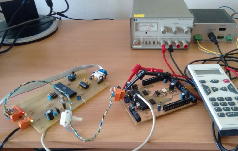
A first test setup is shown above. The Lenz LZV100 digital main station + included booster transmits continous DCC data out to the tracks. The locomotives themselves are controlled via the LH100 hand held controller. The station continiously repeats the last transmitted messages on the tracks to make sure that even when some frames are lost by transmission errors some of them will reach the decoder in the locomotive. There is now way for the main station to know if the control command reached the target receiver or not.
The DCC output signal of the main station is directly connected to the DCC decoder input port pins. The DCC decoder PCB is supplied via a small HP power supply with +5V. Because this board is missing the necessary RS232 interface line driver IC the TTL logic level serial port signals are connected to the AT89S52 programmer board and converted there to the proper serial port logic levels by a MAX232 device.
DCC sniffer firmware
I used the already present DCC decoder AT89S52 firmware as a starting point for the DCC sniffer. Soon I found out that this firmware is to slow for continious decoding of all present DCC frames even thought I already removed unnecessary functions from the source code. There was just too much data copying going on between the different buffers and as a sideeffect also a lot of frames were missed or not received properly. Step by step I modified the source code, and at the end the final outcome had not much in common anymore with the original DCC decoder firmware.The firmware waits for a proper DCC preamble, if one is received the input data is decoded byte by byte. As soon as a full byte was received it is immediately written to the serial port. The whole firmware is completely interrupt driven including the serial port or the DCC decoding via timer to unload the CPU. The main execution loop itself is completely empty. The microcontroller transmits every DCC data byte to the PC and is not aware about the contents or the meaning of the data as this would cost only resources and is also not necessary because the PC takes care of the actual interpretation of the data. Additionaly the microcontroller does no checksum checks on the received data as we also want to see checksum errors on the PC and we do not want to filter them out.
Frame synchronization
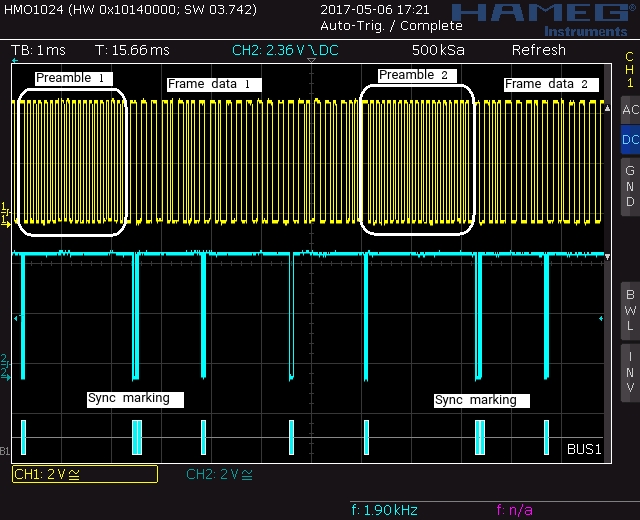
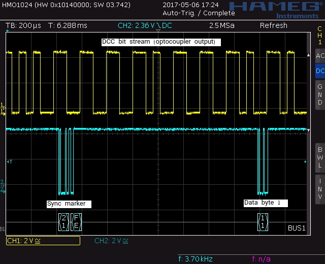
The PC software receives an endless stream of decoded DCC frame bytes. To be able to interpret them properly the PC needs to know where a new DCC frame started and where it ends. That means the data stream must be marked somehow by the microcontroller when a new frame started. Simplest solution would be to use a character which can not exist in the DCC data stream itself, but unfortunetly each DCC byte can have every value between 0 and 255 decimal, and the UART transmission is also only 8-bit wide. That means a clean solution is not so straight forward, and the techniques which can be used to solve this problem will most likely overwhelm the limited resources of the microcontroller. What I did at the end is not a 100% clean solution, but in my oppion it is good enough: I selected two characters which are inserted into the data stream by the uC in a certain order to mark the start of every received DCC frame. Of course it could happen accidently that the transmitted DCC data contains the same characters sequence and would be interpreted as a wrong frame start, but with increased sequence length this probability will get smaller and smaller. Right now the DCC sniffer works perfectly fine with this solution, but it could be that one day you run into a specific transmitted DCC command which will not be understood properly by the PC and will be always marked as a DCC checksum error frame. If this happens all the time this could be the root cause for it.

PC software
The actual interpretation of the received DCC raw data is done by the PC software. It is based on Qt and was developed using Qt5 Creator on my Opensuse Leap 42.2 system. Receiving of the serial data is done using the QtSerialPort class. Because Qt is platform independent it could mean that this source code could also be recompiled and used under other major operating systems. But I have not tested this.
