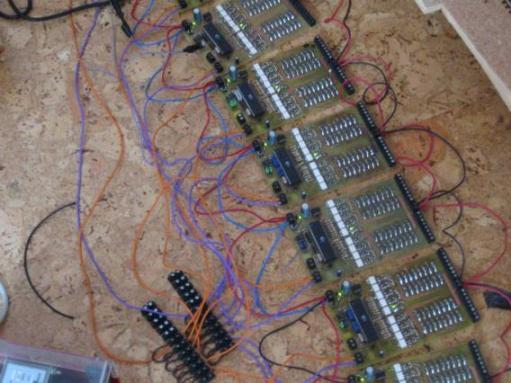
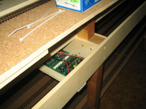
Occupancy detector
Function
This module will be used on the model railroad to detect the train movement and to know which rails/blocks are occupied and which are free. Hence the name occupancy detector. There are many different ways how one can find out if a piece of rail is occupied or not. In my case I use the method which is based on detecting current flow into a piece of rail. If a block is completely empty no load is present across the rails and therefore no current flow is present. The occupancy detector will detect if a piece of track is occupied or not. As soon as a locomotive with a digital decoder is put on the tracks it needs a certain supply current (even when the loco is not moving) which is detected by the circuitry and a message is transmitted via the digital bus to inform the control station that the block is now occupied.There is also a solution to be able to detect a wagon which of course would normally need no current on the model railroad and therefore would be undetected initially. There is some varnish available which is carefully painted onto the plastic axle between the two wheels, and which starts to conduct a little bit of current when cured. Even a current as low as 1mA will be detected by the occupancy detector. Care has to be taken that not to much varnish is applied to the axle, because with increasing thickness the resistance between the wheels can quickly get much to low, and way to much current would flow in this case.
But why do we need this train detection in the first place? The computer needs to know where tracks are occupied or where trains are moving if we want to let the computer control trains automatically. The occupancy detector information is basically all information the computer has to control the trains. Therefore reliable functionality of the detectors is a must.
Lenz RS-Bus
There are many different manufacturers of mode railroad electronics out there, many different protocols and bus systems. The system and bus system we use was created by the german company Lenz. The proparitary digital bussystem of Lenz which carries the occupancy detection event information to the control station is called Lenz RS-Bus. Lenz also sells a printed circuit board to customers which does exactly what my own designed board does. The only reason why I made my own board was that the finished product is much more expensive, and also the cabling is much more work with the Lenz PCB, because their solution does not consist of a single board, but instead of 10 boards which have to be connected together again with wires to get the same 16 inputs like my own board offers.When I started to work on the first prototype for this board a long time ago (I think in 2002, I was still in school) my first big challenge was to find out how the proparitary RS-bus works. At this point in time there was no information about it on the internet as today. I only found two other small private electronic companies in the Internet offering their own product with the RS-Bus to customers to earn money. So I knew it was possible to reverse engineer the protocol. What I did first was to buy one of the modules from Lenz and try to reverse engineer the bus. Only problem was at this point in time my lack of more sophisticated test equipment. The only scope I had was an analog scope with 20 MHz bandwidth. With this scope alone it was almost impossible to find out how the data is transmitted to the central station. To still find out what is going on I decided to take a 8032 microcontroller board I had from school, and I wrote a small firmware which uses the internal 8032 timer and an GPIO pin to try to measure the timing on the signals between the edges, and then output this information via the RS232 microcontroller port to my PC for different scenarios.
With this crude technique I was able to get the first information about the bit order on the RS-bus, the protocol and the used bit duration. With this first findings I was able to write a first test firmware which was able to transmit first events to the control station. But one problem remained: When the central station is powered on all occupancy detectors must first indicate that the are present and only after this the central station will be able to detect, adress and use them. My first firmware program was only able to work after the original Lenz PCB was already connected to the central station and made the necessary contact with the central station before. To find out how this inital contact must be done to finally get the board working completely was much more work, but at the end after a lot of experimentation I had a fully working firmware.
Hardware
First I made an attempt to build the circuitry for current detection completely myself without looking at all at the Lenz solution. My own circuit was working but when I compared it with the solution from Lenz I saw that their design was much smaller and used way less parts. This is when I decided to reverse-engineer their input channel solution, try it out, and just use it instead of my own idea. The final board uses my design for the control circuitry & my firmware, and a similar design for the input current detection like Lenz does. Everything together creates the occupancy detector with 16 input channels.Because the current detection input circuitry is based on Lenz proparitary design I do not want to show it here. This is also the reason why it is missing in the schematic below. The RS-bus interface is still shown here, because it is described already on another website in full-detail.
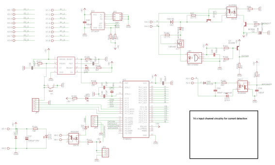
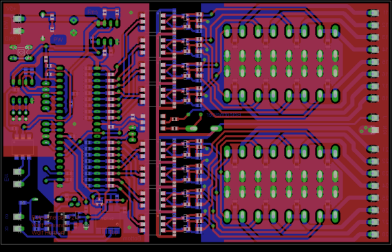
Layout
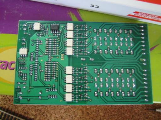
I used my private non-commerical Eagle-License I bought some years ago to make a layout for the final board. When I worked on the first prototype a long time ago I decided to use a AT89S52 microcontroller in the DIP40 package because I got it for only 1.6 Euro per piece. Today I would not use a DIP40 package anymore, and I would pick a slightly more powerful microcontroller with internal EEPROM etc. But because I had already bought a lot of microcontrollers for the final PCBs I had to keep this one in the design and use an external EEPROM instead.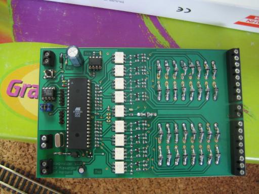
Firmware
The firmware was developed in C, and has the following main tasks: debounce all the input channels, detect input change events and transmit them to the control station via the RS-Bus. The board also has a configuration mode where the two necessary RS-Bus adresses can be configured via a RS232 connection with the PC. This two adresses are then stored in the external EEPROM. Because of proparitary reasons again I do not want to upload this firmware here, because it also handles the proparitary RS-bus interface. Final programming of the PCB is done with my AT89S52 programmer board also introduced on this website.Installation
Around the year 2005 I did the first test runs with more boards in parallel. I etched all of this first boards by hand at home, and then I drilled and populated them. The tests went well and this first boards were finally installed on the model railroad installation. The next PCBs were already ordered at a PCB manufacturer, because it was way to much work and mess to etch all of this boards at home. Populating all the parts still took weekends of work at home. The final model railroad installation has over 300 independent isolated tracks which have to be monitored and therefore I will have to install at least 19 of this occupancy detector boards.